






- Navigation -
 Current Location:
NEWS DETAILS
NEWS INFORMATION
How to Verify the Accuracy of a New Welding Platform on Delivery
AUTHOR:Bozhong Tool DATE:2026-08-26 15:17:23 HITS:98
Accepting a new welding platform — whether a precision surface plate, a modular 3D grid table, or a heavy steel fabrication platform — without a formal incoming inspection is one of the most common and costly oversights in fabrication equipment procurement. A table that appears visually acceptable can harbor flatness deviations, dimensional errors, or casting defects that will compromise workpiece accuracy from day one of production. Without documented acceptance testing, the buyer has no evidence base for a warranty claim if problems emerge weeks or months later.
This article provides a systematic step-by-step process for verifying welding table accuracy on delivery. It covers the instruments required, the measurement procedures, the documentation standards, and the decision criteria that determine whether a delivered platform passes or fails its incoming acceptance test. The procedures described are aligned with international standards including ISO 1101, ASME B89.3.4, and the AWS D1.1 quality requirements referenced by most precision fabrication specifications.
Pre-Inspection Preparation: Setting the Conditions for Valid Measurement
Before any measurement is performed, the table must be given adequate time to equilibrate to the shop environment. A table that has been transported in a cold or hot truck and immediately placed in a climate-controlled or hot fabrication shop will exhibit thermal bow — a false flatness error caused by the temperature gradient between the table surface and its body. This bow can easily exceed the table's tolerance specification and lead to an incorrect rejection decision.
The equilibration requirement is a minimum of 4 hours for tables under 500 kg, and 24 hours for large precision surface plates or heavy grid tables over 500 kg. Ideally, the table should be placed in its final installation position during equilibration, as moving a loaded table can introduce temporary deflection. During equilibration, the table should remain uncovered — closing the table into a crate or wrapping it in insulating material traps heat differentials and prevents proper temperature equalization.
The measurement environment should be as thermally stable as practical. Avoid measuring in direct sunlight, near active heat sources (plasma cutters, furnaces), or in areas with significant air movement or drafts. If the shop has significant thermal variation between morning and afternoon, schedule incoming inspection for mid-morning when the shop temperature is most stable. Record the ambient temperature and relative humidity at the time of measurement as part of the inspection record.
Visual and Physical Inspection: Surface Condition and Casting Quality
The first phase of incoming inspection for welding platforms is a systematic visual and tactile assessment of the surface and casting condition. This phase identifies defects that may be immediately disqualifying or that will require remediation before the table is placed in service.
Visually inspect the entire working surface for: rust spots or active oxidation (particularly in corners and around grid holes), pitting or cratering from foundry defects or handling damage, chips or cracks at grid hole edges (in modular tables), surface scratches or gouges that could interfere with workpiece placement, and evidence of welding repair or patching on the working surface (a significant quality red flag indicating the manufacturer attempted to remediate a casting defect).
Run a clean, dry finger across key areas of the surface to detect surface roughness irregularities that are not visually apparent. For modular grid tables, check that all grid holes are clear of casting sand, swarf, or debris — compressed air is the most effective tool for clearing holes. Inspect the hole edges for burrs or deformations that could interfere with clean insertion of clamping elements. For cast iron plates, apply a small amount of precision blue developer or layout dye to the surface, spread it thin with a clean cloth, and check for localized high spots or surface irregularities revealed by uneven dye coverage.
Examine the table underside, ribbing, and any machined mounting faces for visible cracks, porosity at rib junctions, or evidence of repair welds. The structural integrity of the table base is as important as the working surface — a crack propagating through the rib structure will eventually manifest as surface distortion even if the initial flatness measurement is acceptable.
Flatness Measurement: Autocollimator and Electronic Level Methods
Flatness verification is the core acceptance test for any precision welding platform. The two internationally recognized methods are the autocollimator traverse method and the electronic level method, both described in ASME B89.3.4 and ISO 1101.
The autocollimator method uses a precision optical instrument mounted at one corner of the plate, sighting along a series of traverse lines across the plate surface. A reflecting target is moved along each traverse line, and the autocollimator measures the angular deviation of the reflecting surface from horizontal. These angular measurements are mathematically integrated to calculate the flatness deviation across the plate. This method is highly accurate (resolution to 0.1 arc-second) and is the preferred method for Grade 1 and Grade 0 precision plates.
The electronic level method uses a precision two-axis electronic level to measure the slope of the plate surface along a grid of traverse lines. The level is moved and re-leveled along each traverse, and the slope data is integrated to reconstruct the surface profile and calculate flatness deviation. This method is more practical for workshop-level inspection, requires less specialized training than autocollimator operation, and provides adequate accuracy for Grade 2 and Grade 3 acceptance testing.
For modular grid welding tables, a practical field alternative is the precision straightedge and feeler gauge method. Place a certified precision straightedge on the table surface at multiple orientations (diagonal, transverse, longitudinal), and measure the maximum gap under the straightedge using precision feeler gauges. This method does not provide a quantitative flatness deviation in mm/m, but it does detect deviations that exceed the straightedge tolerance at a specific location. It is useful as a rapid pass/fail screening test before committing to a full autocollimator or level survey.
Hole Pattern and Dimensional Inspection
For modular 3D welding tables, the accuracy of the hole grid is as important as the flatness of the working surface. Dimensional errors in hole spacing, hole diameter, or hole axis perpendicularity will propagate directly into workpiece positioning errors during fixture setup.
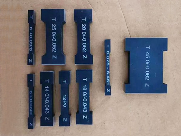
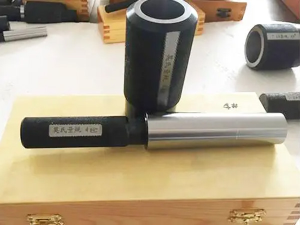
Hole diameter should be verified with a precision bore gauge or pin gauge at a minimum of 10% of the grid holes, distributed across the table surface. The measured diameter should fall within the manufacturing tolerance specified by the grid standard (D16: typically 16 H8, D28: typically 28 H8). Excessive variation in hole diameter — indicating poor drilling quality or drill wear during production — should be documented and flagged for supplier follow-up.
Hole spacing should be verified with calipers or a coordinate measuring arm at a minimum of 5 rows and 5 columns distributed across the table. The measured spacing should conform to the grid standard specification (16 mm or 28 mm, within ±0.1 mm for precision tables). Systematic spacing errors — indicating a calibration error in the original drilling operation — should be documented and discussed with the supplier.
Hole axis perpendicularity should be verified on a sample of holes using a precision square and feeler gauge or a dedicated perpendicularity gauge. A hole that is drilled at an angle will cause clamping elements to sit at an angle, reducing their effective clamping height and compromising their retention force. The perpendicularity tolerance for precision grid tables is typically 0.05 mm per 10 mm of hole depth.
Documentation Requirements and Acceptance Decision Framework
Every welding platform acceptance test must produce a documented record — not only for quality assurance purposes but because it forms the evidentiary basis for any warranty claim against the supplier. An undocumented acceptance test provides no protection if dimensional problems emerge six months later.
The acceptance test report should include: table identification (manufacturer, model, serial/batch number, order number), date and time of inspection, ambient temperature and relative humidity at time of inspection, name and signature of the inspector, instrument identification (instrument type, serial number, last calibration date), measurement results for each parameter inspected (flatness, hole diameter, hole spacing, perpendicularity), comparison of results against specified tolerances, overall acceptance decision (Accept / Accept with Conditions / Reject), and any noted defects or observations.
The acceptance decision framework is straightforward: if all measured parameters fall within specified tolerances, accept the table and place it in service. If any parameter exceeds the tolerance but the deviation is minor and does not affect the table's fitness for the intended application, accept with conditions — document the deviation, notify the supplier, and monitor the affected parameter during future calibrations. If any critical parameter (flatness for precision tables, hole diameter for modular tables) exceeds tolerance by more than a specified minor deviation amount, reject the table and initiate the supplier warranty or replacement process.
For tables sourced internationally — for example, precision welding platforms manufactured by Bozhong Tool in Hebei, China — the acceptance test documentation is particularly critical given the complexity and cost of return logistics. Performing a thorough incoming inspection before accepting delivery from the carrier, and documenting any transit damage observed before opening the crate, provides the evidence needed to pursue carrier insurance claims and supplier warranty claims simultaneously.
Establishing an Ongoing Calibration Schedule
Acceptance testing is the beginning, not the end, of the calibration lifecycle. A new welding platform accepted at Grade 1 flatness does not remain at Grade 1 indefinitely — the aging mechanisms described in this article's companion pieces will gradually push it toward Grade 2, and eventually beyond. Establishing a calibration schedule from the day of acceptance ensures that flatness degradation is detected and corrected before it impacts workpiece quality.
The initial post-acceptance calibration should be performed at 90 days to establish a baseline — this short-interval check reveals whether the table's flatness is stable or whether it has already begun drifting from thermal equilibration after leaving the factory environment. Subsequent calibrations should be scheduled based on the observed aging rate: tables in stable environments with moderate use may require calibration only quarterly; tables in hot, heavily loaded production environments may need monthly checks.
Maintaining a calibration log for each table — with each entry recording the date, measured flatness deviation, ambient conditions, and the inspector's name — builds a data set over time that reveals the table's aging trajectory and informs maintenance decisions. A table whose flatness is drifting steadily toward the tolerance limit is a table that needs re-scraping scheduled; a table whose flatness is stable over multiple calibration cycles is a table that is operating within its design environmental and load envelope.
ASME B89.3.4 — American National Standard for the Care and Calibration of Fixed-Length Surface Plates. New York: American Society of Mechanical Engineers, 2009. ISO 1101:2017. Geometrical product specifications (GPS) — Geometrical tolerancing — Tolerances of form, orientation, location and run-out. International Organization for Standardization, 2017. British Standards Institution. BS EN ISO 9013:2017 — Thermal cutting — Classification of thermal cuts. London: BSI, 2017. American Welding Society (AWS). Structural Welding Code — Steel (AWS D1.1/D1.1M). Miami: AWS, 2020. ISO 14284:1996. Steel and iron — Sampling and preparation of samples for the determination of chemical composition. International Organization for Standardization, 1996. ISO 2768-1:1989. General tolerances — Part 1: Tolerances for linear and angular dimensions without individual tolerance indications. International Organization for Standardization, 1989. ASTM A48/A48M-03. Standard Specification for Gray Iron Castings. West Conshohocken: ASTM International, 2003.References
-
Welding Table Surface Hardness — What Rockwell and Brinell Numbers Mean for Buyers
-
Welding Table Load Capacity — Understanding Static and Dynamic Ratings
-
Modular Welding Table ROI — Calculating Return on Investment for Fabrication Shops
-
Industrial Metrology Basics for Welding Fabrication — Standards, Tools, and Workflows
-
Granite Surface Plate Calibration — Frequency, Methods, and Standards
-
How to Design a Welding Fixture from Scratch — A Step-by-Step Engineering Guide
Botou Bozhong Precision Machine Tool Co., Ltd.
Copyright © 2025-2026 https://www.bozhong-weldingtable.com. All Rights Reserved Botou Bozhong Precision Machine Tool Co., Ltd.Copyright