


- Navigation -
 Current Location:
PRODUCTS DETAILS
PRODUCTS DISCRIPT
-
Welding Table
-
Machine Tool Casting
-
Cast Iron Surface Plate
-
Granite Surface Plate Measuring Tools
-
Machine Tool Leveling Pad
-
3D Platform Accessories
-
Plug Gauge/Ring Gauge
-
Bent board/square box
-
Machine Tool Test Bar
-
Magnesium-Aluminum Straightedge
-
Cast Iron Straight Edge/Square
-
Welding displacement series
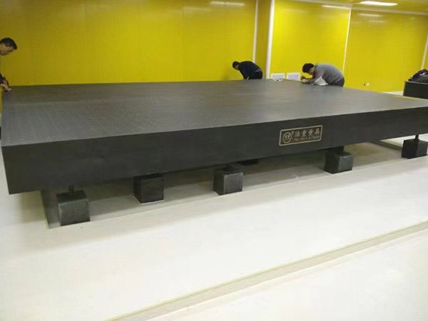
Large spliced granite slab customer is now installing
Installation Guidelines for Large Spliced Granite Slabs When customers install large spliced granite slabs—commonly used in precision measurement platforms, aerospace assembly sta......


 PRODUCT DETAILS
Installation Guidelines for Large Spliced Granite Slabs
When customers install large spliced granite slabs—commonly used in precision measurement platforms, aerospace assembly stations, or semiconductor inspection lines—strict adherence to installation protocols is critical to ensure flatness, stability, and long-term performance. Below is a step-by-step guide tailored to on-site installation scenarios, addressing key challenges and best practices.
1. Pre-Installation Preparation
Site Assessment
Foundation Inspection: The installation surface (typically a reinforced concrete foundation) must have a flatness tolerance of ≤2mm/m and load-bearing capacity exceeding 50kN/m² (for slabs over 5m in length). Use a laser level to map high/low points and grind uneven areas to avoid stress concentration in the granite.
Environmental Control: Ensure the installation area is clean, dust-free, and temperature-stable (20±2℃). Sudden temperature changes (>5℃/hour) can cause thermal expansion mismatches between spliced slabs.
Tool Calibration: Verify the accuracy of installation tools—including laser interferometers (±0.001mm/m), precision shims (0.01mm increments), and torque wrenches (calibrated within ±2% error)—to guarantee measurement reliability.
Slab Inspection
Dimensional Checks: Confirm each granite slab’s flatness (≤0.01mm/m for precision grades) and edge straightness (≤0.005mm/m) using a master straightedge. Reject slabs with visible cracks, delamination, or uneven polishing.
Splicing Surface Preparation: Clean the mating edges of each slab with alcohol to remove dust or residue. Use a profilometer to ensure edge parallelism; gaps between spliced edges must be ≤0.02mm to prevent vibration-induced wear.
2. Splicing & Alignment Process
Lifting & Positioning
Crane Handling: Use vacuum lifters with distributed suction cups (each rated for ≥500kg) to avoid stressing the granite, which is brittle (tensile strength ≈10-20MPa). Lift slabs vertically and lower them slowly onto temporary supports (rubber-padded steel frames) to prevent impact damage.
Initial Alignment: Place slabs on pre-installed adjustable supports (3-4 per m²) and roughly align their edges using alignment pins (diameter tolerance H7/g6) inserted into pre-drilled holes (≤0.01mm positional error).
Precision Leveling
Flatness Calibration: Deploy a laser tracker to measure the combined surface of spliced slabs. Adjust each support’s height via micrometric screws (0.01mm per turn) to achieve a global flatness of ≤0.03mm/m. Prioritize leveling in the following order:
Level individual slabs first to their local datum.
Align adjacent slabs at splicing seams, ensuring no step difference (≤0.005mm) using a feeler gauge.
Stress Relief: After initial leveling, leave the slabs undisturbed for 24 hours to allow internal stresses to dissipate. Recheck flatness; minor adjustments (≤0.003mm) may be needed due to creep in support systems.
3. Splicing & Fixing
Seam Treatment
Adhesive Application: Use low-shrinkage epoxy (e.g., 2-part structural epoxy with <0.1% shrinkage) to bond splicing edges. Apply a 0.1-0.2mm thick layer using a precision syringe, ensuring full coverage without excess (which could cause bulging).
Clamping: Secure adjacent slabs with non-magnetic stainless steel clamps (spacing 300-500mm along seams) with controlled pressure (5-8kN) to avoid cracking. Use Teflon pads between clamps and granite to prevent surface scratches.
Anchoring to Foundation
Flexible Fixing: Attach slabs to the foundation using slotted anchor brackets (allowing ±0.5mm thermal movement) and vibration-damping washers (urethane, 50 Shore A hardness). Avoid rigid bolting, as granite’s low thermal expansion (5×10⁻⁶/℃) differs from concrete’s (12×10⁻⁶/℃), risking cracking.
4. Post-Installation Verification
Flatness Testing
Grid Measurement: Divide the spliced surface into 500×500mm grids and measure each node with a laser interferometer. The maximum deviation across the entire surface must not exceed 0.02mm/m.
Seam Integrity Check: Use a 0.005mm feeler gauge to test for gaps at seams—no penetration indicates proper bonding.
Vibration & Load Testing
Dynamic Load Test: Apply 80% of the maximum rated load (e.g., 20 tons for a 6m×3m slab) uniformly across the surface and monitor deflection with strain gauges. Permanent deformation must be <0.001mm.
Vibration Damping Check: Use accelerometers to measure resonance frequency (typically 50-80Hz for granite). Ensure no overlap with operational frequencies of adjacent machinery (e.g., CNC tools, robotic arms).
5. Common Installation Challenges & Solutions
Challenge
Cause
Solution
Seam step difference (>0.01mm)
Uneven foundation or slab warpage
Grind high spots on the slab edge using a diamond wheel (≤0.005mm removal) and re-level with shims.
Adhesive overflow
Excessive epoxy application
Use a razor blade to trim excess before curing; polish residual with 3000-grit diamond pads.
Thermal-induced stress
Temperature fluctuations during installation
 2026-07-07
Botou Bozhong Precision Machine Tool Co., Ltd.
Copyright © 2025-2026 https://www.bozhong-weldingtable.com. All Rights Reserved Botou Bozhong Precision Machine Tool Co., Ltd.Copyright