






- Navigation -
 Current Location:
NEWS DETAILS
NEWS INFORMATION
Clamping and Fixturing Systems for 3D Welding Tables: A Design Guide
AUTHOR:Bozhong Tool DATE:2026-07-13 19:33:21 HITS:99
In high-volume fabrication, the quality of a weld is only as good as the fixture that holds the workpiece. Even the most skilled welder operating with perfectly tuned equipment will produce inconsistent, dimensionally non-compliant results if the workpiece is not held firmly, repeatably, and in the correct spatial orientation. This is why the design and implementation of clamping and fixturing systems for 3D welding tables is one of the most impactful decisions a welding engineer or production manager can make.
A well-designed modular fixturing system on a 3D flexible welding table transforms a general-purpose platform into a precision manufacturing cell capable of producing consistent results across thousands of production cycles. Conversely, a poorly designed fixture — one with insufficient clamping force, incorrect workpiece orientation, or inadequate support — introduces dimensional errors, weld distortion, and production delays that cascade through the entire manufacturing process.
This guide provides a comprehensive, engineering-grounded introduction to clamping and fixturing systems for 3D welding tables. It covers the fundamental role of fixturing in precision welding, the range of available clamping technologies, practical methods for calculating and specifying clamping force, strategies for minimising fixture setup time, and design principles for building a reusable fixture library. Whether you are a welding engineer specifying a new production fixture, a fixture designer working to modular standards, or a production manager looking to reduce changeover time on your shop floor, this guide provides the technical foundation you need.
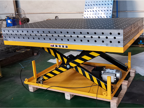
The Role of Fixturing in Precision Welding
Fixturing in welding serves multiple simultaneous functions that are often underestimated in their complexity. A fixture must do more than simply hold a workpiece in place — it must resist the substantial forces generated by the welding process itself, maintain precise dimensional relationships between mating components, minimise the distortion introduced by non-uniform heating, and enable consistent, repeatable positioning across multiple production cycles.
The primary mechanical challenges that fixtures must address are:
Welding force reactions: The electromagnetic force (Lorentz force) generated by the welding arc, combined with the冲击力 of molten metal and spatter, creates dynamic loading on the workpiece. A fixture that cannot resist these forces will allow the workpiece to shift during welding, producing misalignment and defects.
Thermal distortion management: Non-uniform heating of the workpiece during welding causes differential expansion and contraction, leading to angular, bow, and twist distortions. Well-designed fixtures use strategic clamping positions and heat sinks to manage these effects.
Gravity and mass effects: For large, heavy workpieces, the fixture must resist gravitational forces and prevent the workpiece from shifting, tilting, or falling during positioning and welding.
Assembly tolerance stacking: In multi-part weldments, the fixture must hold each component in the correct spatial relationship to the others, managing the cumulative effect of individual component tolerances on the final assembly dimensions.
The AWS D1.1 Structural Welding Code — Steel provides specific requirements for minimum preheat temperatures, fit-up tolerances, and inspection criteria that directly influence fixture design for structural steel applications. Similarly, ISO 9692 specifies joint preparation requirements that determine the required positioning accuracy of the fixture for different joint configurations.
Types of Clamping Systems for 3D Welding Tables
The modular nature of 3D welding tables — characterised by precision hole-pattern grids such as the D16 or D28 system — enables the use of a wide variety of clamping systems, each suited to different workpiece types, production volumes, and accuracy requirements. Understanding the strengths and limitations of each clamping type is essential for selecting the right solution.
Step Clamps
Step clamps are among the most versatile and widely used clamping components for 3D welding tables. They engage with the hole-pattern grid on the table surface and use a threaded screw mechanism to apply clamping force to the workpiece from above. Step clamps are available in a range of sizes and clamping heights, with options for flat clamps (for general workpieces) and toe clamps (for clamping at low heights or against vertical surfaces). They are manually operated, require no external power or plumbing, and are suitable for virtually any flat or slightly irregular workpiece surface.
Wedge Clamps
Wedge clamps use a tapered wedge element driven by a threaded screw to apply rapid clamping force. They are particularly useful in production environments where speed is critical, as the wedge mechanism allows faster engagement and disengagement than standard step clamps. However, wedge clamps generally offer less precise force control and are less suitable for applications requiring very consistent, calibrated clamping force.
Toggle Clamps
Toggle clamps use a lever-operated mechanical linkage to lock the clamp in the clamped position with a very high clamping force relative to the handle force applied. They are widely used in production fixture applications where speed and consistency are critical, and they can be quickly released for rapid workpiece changeover. Vertical toggle clamps and horizontal push-pull toggle clamps are the most common configurations for welding table applications.
Cam-Lock and Ratchet Clamps
These clamping systems use a cam or ratchet mechanism to provide rapid engagement and a firm locking action. They are widely available as modular accessories for D16 and D28 hole-pattern welding tables and are suitable for medium-duty clamping applications where the speed advantage over standard step clamps is desirable.
Specialty Clamps: Vise Clamps and V-Block Clamps
For cylindrical or tubular workpieces, V-block clamps and vise-style clamps that engage with the table grid provide a secure, self-centring clamping solution. These are essential for any fabrication operation that processes pipe, tube, or round bar stock on the welding table.
Stop Pins, Blocks, and Positioning Components
Positioning components — stop pins, positioning blocks, and fixture feet — are the foundation of repeatable fixturing on a 3D welding table. They define the fixed reference points against which the workpiece is located, and their accuracy and consistency directly determine the positional accuracy of the workpiece in each setup.
Stop Pins and Dowel Pins
Stop pins are cylindrical elements inserted into the hole-pattern grid of the welding table to provide precise X, Y, and Z datum references for workpiece positioning. They are available in various lengths, diameters, and tolerances — standard tolerance pins for general fabrication and precision-ground pins for high-accuracy positioning. Stop pins are typically manufactured from hardened steel and are designed to withstand the clamping and welding forces without deformation.
For production fixtures, dedicated hardened locating pins can be left in the fixture configuration permanently, providing a fixed datum reference that eliminates the need to re-establish positioning references for each production run. This is one of the key advantages of a modular fixturing system over traditional dedicated welded jigs.
Fixture Feet and Adjustable Feet
Fixture feet attach to the underside of custom fixture plates, sub-fixtures, or dedicated jig plates and locate into the table's hole pattern, providing a stable, repeatable mounting interface. Adjustable levelling feet allow fine height adjustment of fixture assemblies, which is essential for achieving accurate workpiece positioning on tables that may not be perfectly level.
Angle Plates and Riser Blocks: When and How to Use Them
Angle plates and riser blocks are essential fixturing accessories that extend the effective range of the 3D welding table by providing vertical reference surfaces, elevated workpiece support, and compound angle positioning capabilities.
Riser Blocks and Height Extensions
Riser blocks — solid or hollow blocks that locate into the hole pattern and raise the workpiece above the table surface — are used when the workpiece geometry requires clearance below the work area, when operator ergonomics benefit from raising the work to a more comfortable height, or when the welding process requires the workpiece to be suspended above the table to prevent weld spatter damaging the table surface. They are available in standard heights (25 mm, 50 mm, 100 mm, 150 mm) and can be stacked to achieve custom heights.
Angle Plates and Angle Fixtures
Angle plates provide a 90° vertical reference surface against which workpieces can be positioned, squared, and clamped. They are indispensable for positioning flat plates, structural sections, and assemblies at right angles to the table surface. In production welding of frames, boxes, and structural assemblies, angle plates serve as the primary datum reference for maintaining squareness. Adjustable angle plates with protractor scales allow positioning at any angle from 0° to 90°, enabling compound angle setups for complex weldment geometries.
The SME Tool and Manufacturing Engineers Handbook provides comprehensive guidance on the design and application of angle plates, including recommendations for achieving and verifying 90° squareness, and the use of sine plates for precise angular positioning in fabrication.
Calculating Clamping Force Requirements
Properly specifying clamping force is one of the most technically demanding aspects of fixture design. Insufficient clamping force results in workpiece movement during welding; excessive clamping force can deform the workpiece, particularly thin-walled sections or machined surfaces. The correct approach is to calculate the minimum clamping force required to resist all acting forces and then select a clamping solution that comfortably exceeds this value with an appropriate safety margin.
Identifying Acting Forces
For welding fixture design, the forces that the clamp must resist typically include:
Welding arc force: The electromagnetic force of the welding arc, which for typical MIG/MAG welding is in the range of 5–30 N depending on current and arc length
Gravity and workpiece mass: The weight of the workpiece acting through its centre of gravity
Clamping reaction to thermal expansion: As the workpiece heats during welding, it expands; the fixture must resist this expansion to maintain joint fit-up
Process forces: For processes such as plasma cutting or grinding performed on the table, additional process-specific forces must be considered
Simple Force Balance Calculation
A practical approach to clamping force calculation for manual welding fixtures is to establish a force balance using a safety factor of 2–3. For most flat workpiece clamping scenarios on a horizontal welding table:
Minimum Clamping Force (Fclamp) ≥ Fgravity + Farc × Safety Factor
Where Fgravity = mass (kg) × 9.81 m/s² and Farc is estimated from welding parameters.
Example: A 20 kg steel plate on a horizontal table requires Fgravity = 196 N. With estimated arc force of 15 N and safety factor of 3: Fclamp ≥ 196 + (15 × 3) = 241 N minimum per clamp location. A standard step clamp generating 2,000–5,000 N of clamping force easily satisfies this requirement.
For thin-walled workpieces where deformation is a concern, the clamping force must be limited to a value that provides secure restraint without exceeding the workpiece's local buckling threshold. In these cases, the use of shaped protective pads between the clamp and the workpiece surface distributes the clamping force more evenly and reduces the risk of local deformation.
Pneumatic vs. Hydraulic vs. Manual Clamping
The choice between pneumatic, hydraulic, and manual clamping systems involves a trade-off between speed, clamping force, cost, system complexity, and flexibility. Each system has a defined application envelope:
For most general fabrication operations using 3D welding tables, manual step clamps and toggle clamps provide the best balance of flexibility, cost, and clamping performance. Pneumatic clamping becomes attractive when production volumes justify the investment in air supply infrastructure and when fast changeover between part variants is required. Hydraulic clamping is reserved for the heaviest fabrication applications — thick plate welding, large structural assemblies, and operations where the sustained high clamping force is required to resist significant thermal distortion.
Fixture Setup Time: How to Minimise Changeover
Fixture setup time — the elapsed time between completing one production run and starting the next — is a major contributor to non-value-added time in fabrication shops. In job-shop environments where part variety is high, reducing setup time is a critical competitiveness factor.
Strategies for minimising fixture setup time on 3D welding tables include:
Standardised hole-pattern grids: The universal nature of D16 and D28 hole-pattern systems means that any compatible fixture component — stop pins, clamps, angle plates, risers — can be positioned at any grid point. This eliminates the need for bespoke fixture manufacture for each new part variant and allows fixtures to be configured in minutes rather than hours.
Pre-built fixture configurations: Document and photograph the fixture configurations for each part number, including the positions of all pins, angle plates, risers, and clamps. This creates a visual setup guide that allows any trained operator to re-establish the fixture in minimal time.
Dedicated sub-fixtures: For high-volume part families, consider fabricating lightweight sub-fixture plates that locate into the main table grid and carry the dedicated fixture hardware. Swapping sub-fixtures can reduce setup time to under 5 minutes for many part types.
Quick-release clamping: Replacing standard fasteners with quick-release clamp designs, Dzus-style fasteners, or magnetic clamping plates for non-ferrous workpieces can significantly reduce mechanical setup time.
Parallel preparation: While the current production run is underway, prepare the fixture for the next run — positioning pins, angle plates, and clamps on a staging table — so that changeover requires only installing the pre-prepared configuration on the main table.
Designing Reusable Fixture Configurations
One of the most powerful advantages of modular 3D welding table fixturing is the ability to design fixture configurations that are reusable across similar part variants, reducing the total number of unique fixtures required and simplifying fixture management. Effective reuse design requires systematic thinking about the geometric and functional commonalities between parts.
Key principles for designing reusable fixture configurations:
Identify common datums: Parts within a family often share one or more datum features. Design fixtures that use these common datums as the primary locating surfaces, allowing different parts to be fixtured with minimal reconfiguration.
Design adjustable elements: Incorporate adjustable stop pins, sliding locating elements, and modular risers that can accommodate dimensional variation between parts within a family without requiring a new fixture design.
Use modular sub-assemblies: Design fixture sub-assemblies (such as a four-sided frame positioning set, a tube-centring V-block assembly, or a panel-clamping frame) that can be stored as discrete units and combined in different configurations to support different part geometries.
Document and number everything: Assign part numbers and drawing references to each fixture configuration. Maintain a fixture register that maps part numbers to fixture configuration references and storage locations.
Common Fixturing Mistakes in Fabrication
Avoiding the following common mistakes will significantly improve the quality and repeatability of welding fixtures in fabrication environments:
Insufficient clamping force: The most common fixturing failure mode. Always calculate the required clamping force and verify that the selected clamp can deliver it comfortably.
Poor datum selection: Using an unstable or irrelevant datum feature as the primary locating reference leads to inconsistent positioning. Always select datums that are accessible, stable, and common to the part's design reference frame.
Clamping too close to the heat-affected zone: Clamping directly adjacent to the weld joint restricts thermal expansion during welding, which can cause cracking in the HAZ or the weld metal. Position clamps away from the joint — typically a minimum of 50 mm from the weld centreline for plate thickness up to 20 mm.
Over-constraining the workpiece: Applying too many clamps in incompatible directions can introduce residual stresses in the workpiece before welding even begins, compounding distortion during the welding process. Apply the 3-2-1 principle of fixturing: three points on the primary face, two on a perpendicular face, one on a third face.
Ignoring workpiece deformation under clamping: Thin sections, machined surfaces, and welded assemblies with internal stresses can deform when clamped. Use protective pads, broad-based clamp feet, and even clamping force to distribute load safely.
Not providing access for welding: A fixture that holds the workpiece securely but prevents the welder from accessing the joint is useless. Design fixture access routes for each weld in the production sequence before finalising the fixture layout.
Building a Fixture Library for Your Production Line
A well-managed fixture library — a systematically organised collection of documented fixture configurations and reusable fixturing components — is a significant operational asset for any fabrication facility. It transforms fixturing from an ad hoc activity into a structured, repeatable engineering process.
Building an effective fixture library involves the following steps:
Audit existing fixtures: Document every fixture currently in use, including part numbers supported, current condition, location, and any known limitations or historical issues.
Standardise on grid systems: Ensure that all new fixture purchases are compatible with the existing hole-pattern grid system on your welding tables. Mixing incompatible grid standards (e.g., D16 and D28) requires additional adapter components and complicates the fixture library.
Create fixture data sheets: For each fixture configuration, create a fixture data sheet that includes a schematic diagram or photograph of the fixture layout, a parts list of all components used, the rated clamping force, any special operational notes, and the approved part numbers that can be run on this fixture.
Implement a storage and retrieval system: Organise fixture components in labelled, numbered storage bins and locations. A simple numbering system — for example, FL-001 for Fixture Library entry 1 — makes it easy to cross-reference fixture data sheets to physical storage locations.
Schedule regular fixture inspection: Include fixture components in the regular maintenance and inspection schedule. Check stop pins for wear, verify flatness of fixture plates, inspect clamping components for wear or damage, and re-certify fixtures used for precision applications.
Engage with your supplier: Work with an experienced industrial manufacturer or China factory supplier of modular welding table components to access a wide range of standardised fixturing accessories and to obtain custom fabrication services for non-standard fixture components. A reliable supplier relationship ensures that replacement components are available quickly when needed, minimising production interruptions.
The investment in building a structured fixture library pays dividends across the entire production operation: reduced setup time, improved repeatability, faster operator training, lower fixture inventory costs, and fewer quality incidents related to fixturing errors. For industrial manufacturers and fabrication shops committed to lean production principles, the fixture library is a foundational element of a well-run welding workstation.
References
American Welding Society. AWS D1.1/D1.1M: Structural Welding Code — Steel (2020 Edition). AWS, Miami, FL.
International Organization for Standardization. ISO 9013 — Thermal Cutting — Classification of Thermal Cut Edges — Evaluation of Edges and Maximum Values of Roughness. ISO, Geneva.
The American Society of Mechanical Engineers. ASME Y14.5 — Dimensioning and Tolerancing. ASME, New York, 2018.
Oberg, E., Jones, F.D., Horton, H.L. & Ryffel, H.H. Machinery's Handbook (30th Edition). Industrial Press, New York, 2016.
Kalpakjian, S. & Schmid, S.R. Manufacturing Engineering and Technology (7th Edition). Pearson Education, Boston, MA, 2014.
-
Welding Table Surface Hardness — What Rockwell and Brinell Numbers Mean for Buyers
-
Welding Table Load Capacity — Understanding Static and Dynamic Ratings
-
Modular Welding Table ROI — Calculating Return on Investment for Fabrication Shops
-
Industrial Metrology Basics for Welding Fabrication — Standards, Tools, and Workflows
-
Granite Surface Plate Calibration — Frequency, Methods, and Standards
-
How to Design a Welding Fixture from Scratch — A Step-by-Step Engineering Guide
Botou Bozhong Precision Machine Tool Co., Ltd.
Copyright © 2025-2026 https://www.bozhong-weldingtable.com. All Rights Reserved Botou Bozhong Precision Machine Tool Co., Ltd.Copyright